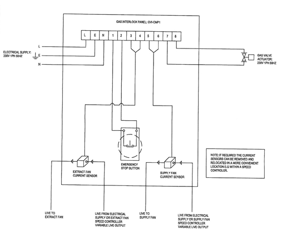
Gas Interlock Wiring Diagram
You need a 3 way switch for the exhaust fan 2 way for the ventilation switch. Describe the meaning of the c13 in the diagram component q.
Gas Interlock System R and B Mechanical and Electrical
Blocked fuel filter signal interlock signal pad wear signal lifted axlesignal.
Gas interlock wiring diagram. Also another set of wires run into the seat bottom. S&s northern is one of the uk's leading designers, manufacturers and suppliers of the latest range of gas safety products including gas ventilation and gas interlock systems for use in commercial kitchens. How to wire a solenoid valve wiring diagram png circuit for connecting the dc with 3 connect plc gas injection using valves cr10 campbell reset electric installation tameson co uk transfer redhat 4 aluminum air and fuel detector vedard security alarm schematic.
Amana gas dryer wiring diagram wiring diagram for whirlpool gas throughout gas solenoid valve wiring diagram, image size 554 x 268 px, and to view image details please click the image. Get access all wiring diagrams car. As contactor m1 energies, it’s all normally close (nc) links open and the other normally open (no) links used in the circuit close.
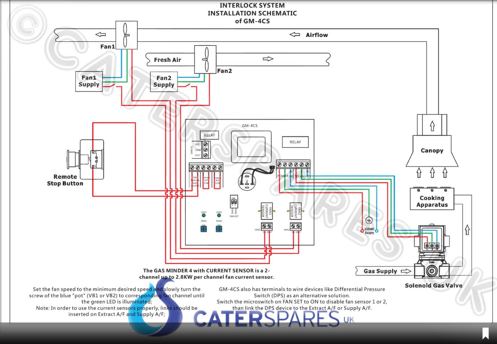
The gas interlock system for commercial kitchens tel: • connect as detailed in wiring diagram (see section 11) gas valve: Of course this situation is also applicable when multiple fuel sources shutdown while in the middle of a sequence of starting another fuel system, which can be a very rare case as the blue moon.
Referring to the wiring diagram, figure 2 on page 8, the operating control and auxiliary limits 1, 2. Get access all wiring diagrams car. • connect 230vac gas solenoid valve as detailed in wiring diagram.
This ensures that the commercial kitchen ventilation system is working before the gas is turned on. By wiring any of twenty interlock switches into the interlock annunciator module, the burnerlogix. Just to finish this up for the curious who search in the future:
The design of the gas minder ensures that there is no gas flow to burners unless air extraction is present. An ip55 rated enclosure is used to house the unit which is designed to operate with a 230 volt gas solenoid and either an appropriate air differential. Gas solenoid valve manufacturers and suppliers china factory yuyao no 4 instrument.
Describe the meaning of the 2 in diagram component s. Wiring diagram book a1 15 b1 b2 16 18 b3 a2 b1 b3 15 supply voltage 16 18 l m h 2 levels b2 l1 f u 1 460 v f u 2 l2 l3 gnd h1 h3 h2 h4 f u 3 x1a f u 4 f u 5 x2a r power on optional x1 x2115 v. Here is a picture gallery about gas solenoid valve wiring diagram complete with the description of the image, please find the image you need.
This panel, air switch, estop and 25mm gas valve £190 + del & vat. Describe the meaning of the s/d in diagram component t. An active fuel, blinks if any gas interlock is open.
Excerpt from section 6.4.1.2.1 of nfpa 85. 3.3l flex fuel, shift interlock wiring diagram for chrysler town & country limited 2010. Factory wiring is in accordance with ul 1995 standards.
• fuse the 230vac power supply according to the fan currents + 2a. Describe and identify the diagram component u. 3.8l, shift interlock wiring diagram for chrysler town & country limited 2010.
I had wired it correctly, just misinterpreted the steps. Interlock connection fixed adjustable fixed res heating element h adjustable, by fixed taps res rheostat, potentiometer or adjustable taps res diode. 100 s gas interlock system.
And motor m1 starts to run. Safety interlock switch wiring diagram. Exhaust fan interlock wiring diagram.
Interlock system diagram for multiple burners. Gas safe regulations and bs6173 both require a gas interlock system to be fitted. Gas interlock system wiring diagram throughout gas solenoid valve wiring diagram by admin through the thousand photographs on the web in relation to gas solenoid valve wiring diagram, we all picks the best series together with greatest quality only for you, and now this photographs is actually among images series within our greatest graphics gallery.
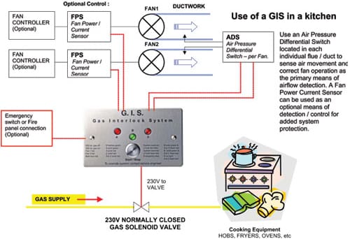
Understanding toyota wiring diagrams worksheet #1 1. This prevents a build up of potentially poisonous gas combustion fumes in the kitchen which would be harmful to the health of kitchen staff and others within the. Prices technical instructions buy now.
Appliance wiring material is a classification of underwriters laboratories inc covering insulated wire and cable intended for internal wiring of appliances and equipment. Call now to order 02381 290444. Connect as detailed in wiring diagram.
We also design and manufacture a full range of gas pressure proving systems and gas detection systems for school laboratories and boiler houses. Control systems hardware / software requirements It shows the components of the circuit as simplified shapes, and the capacity and signal associates between the devices.
The wiring diagram should be in one or the other. The intelligas 100s is the simplest, most economical gas interlock system that we offer.
Exhaust Fan Interlock Wiring Diagram

Gas Interlock Systems
Shay Reproduction Gas Gauge Wiring Diagram

Gas Interlock System Wiring Diagram SIXMILLIONLIES

Smart Start Ignition Interlock Wiring Diagram Complete Wiring Schemas

Gas Solenoid Valve Wiring Diagram Fuse Box And Wiring Diagram

NCSP Gas Ventilation Interlock Panel / NFAN Supply & Stock Extractor Fans & Ventilation
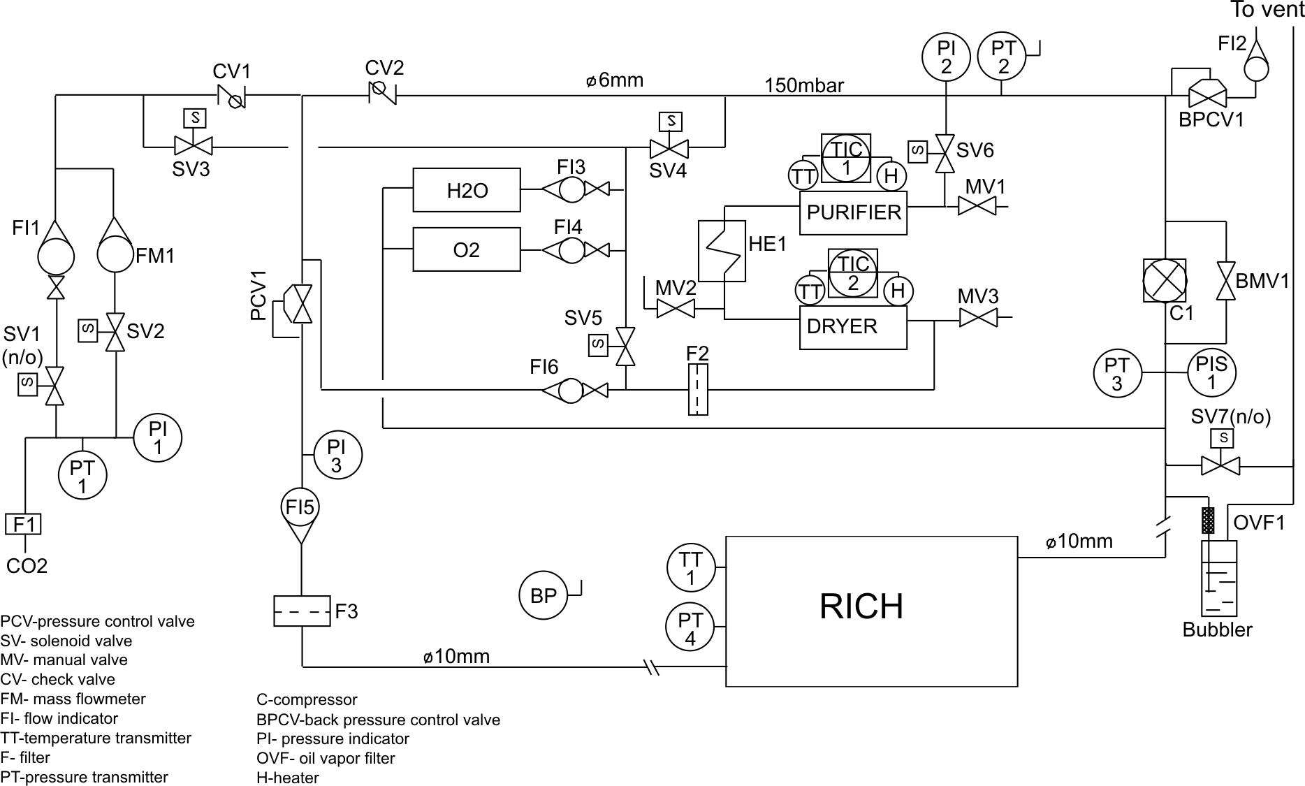
Cryogenic and Superconductive Techniques Laboratory » RICH
Gas Interlock System Wiring Diagram SIXMILLIONLIES

Gas Solenoid Valve Wiring Diagram Fuse Box And Wiring Diagram

Safety Interlock System Installation Instructions

Gas Interlock Control Panel/Ventilation Interlock Control Panel International Gas Detectors

My car will crank with a remote starter but not with the ignition switch

COMMERCIAL GAS INTERLOCK SYSTEM CONTROL PANEL CURRENT MONITORING CONTROLLED UNIT CaterSparesUK
GV 2 Gas Ventilation Interlock Panel / NFAN Supply & Stock Extractor Fans & Ventilation
I have a ezgo gas 4X4. The ignition turned around and the wires came off. Need a wire diagram to

What is a Valve Interlock?

Door Lock Actuator Wiring Diagram Wellread Me And Power Door locks, Electrical wiring diagram

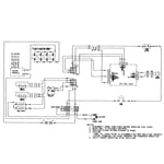
Maytag MGRH752BDB gas range parts Sears PartsDirect