Rectifier Diagram Wiring
The main advantage of this bridge circuit is that it does not require a. 6 wire regulator rectifier wiring diagram.
3 Wire Rectifier Regulator Wiring Diagram Wiring Forums

As i mentioned in the last step the different manufacturers tend to vary their wire colours so you ll need access to a wiring diagram for the make and model your regulator rectifier is off.

Rectifier diagram wiring. Trail tech regulator rectifier 7003 rr150 2 yellow wires. When something is wired “in parallel” it means it is wired alongside a circuit with its own positive wire. Breakers fuses diodes bridge rectifiers wire miscellaneous connectors
Each component ought to be set and linked to different parts in particular manner. We expect that rapid rectifier wiring diagram deliver fresh ideas or references for visitors. Regulator rectifier 7003 rr150 tech support.
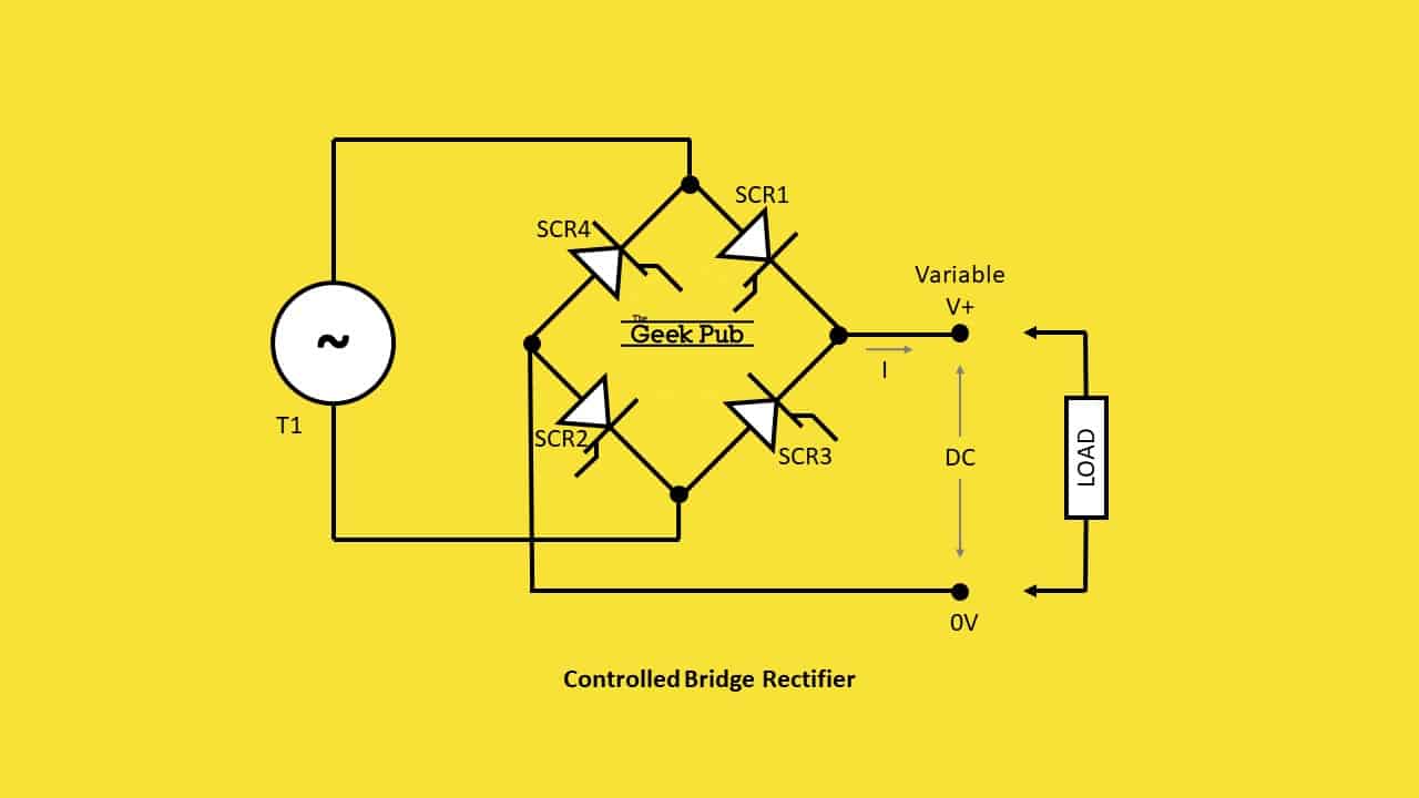
A basic bridge rectifier circuit is shown below. It contains instructions and diagrams for different kinds of wiring strategies as well as other things like lights, windows, and so on. Measurements sun 4 inches l x 1 12 inches w sand 5 inches l x 1 12 inches w ocean 6 inches l x 1 12 inches w.
5 pin rectifier wiring diagram. It contains instructions and diagrams for different kinds of wiring strategies as well as other things like lights, windows, and so on. Also if it's electric start only, your gonna need the start solonoid ,too.
5 pin rectifier regulator wiring diagram. Look for loose connections, signs of arcing, strange odors or discoloration. Ford 6 volt positive ground wiring diagram gmc truck radio wire inside 6 volt positive ground wiring diagram image size 3804 x 1968 px and to view image details please click the image.
010 elv 71 regulatorrectifier 7003 rr150 tech support. The pain really is that all car is different. Wiring diagram consists of numerous comprehensive illustrations that show the link of varied things.
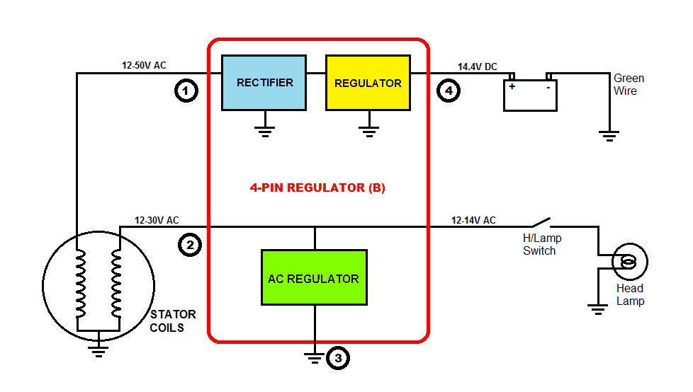
A diagram of the basic bridge rectifier circuit has a bridge rectifier block at the centre. The coil in the diagram is shown attached at one end to earth, then just a few coils up is the green wire take off, then close to the end of the coil is the. Adding a regulator rectifier to an outboard motor so you can charge a battery is a relatively simple job.
When the bike is started through the alternator there is the whole load of current that is produced. There’ll be principal lines which are represented by l1, l2, l3, and so on. Each diagram includes the part and associated parts all in one wiring diagram.
However, it doesn’t mean link between the cables. You need a lighting coil to supply an ac current that the rectifier will convert to a dc. Frontrear brake light switch replacement.
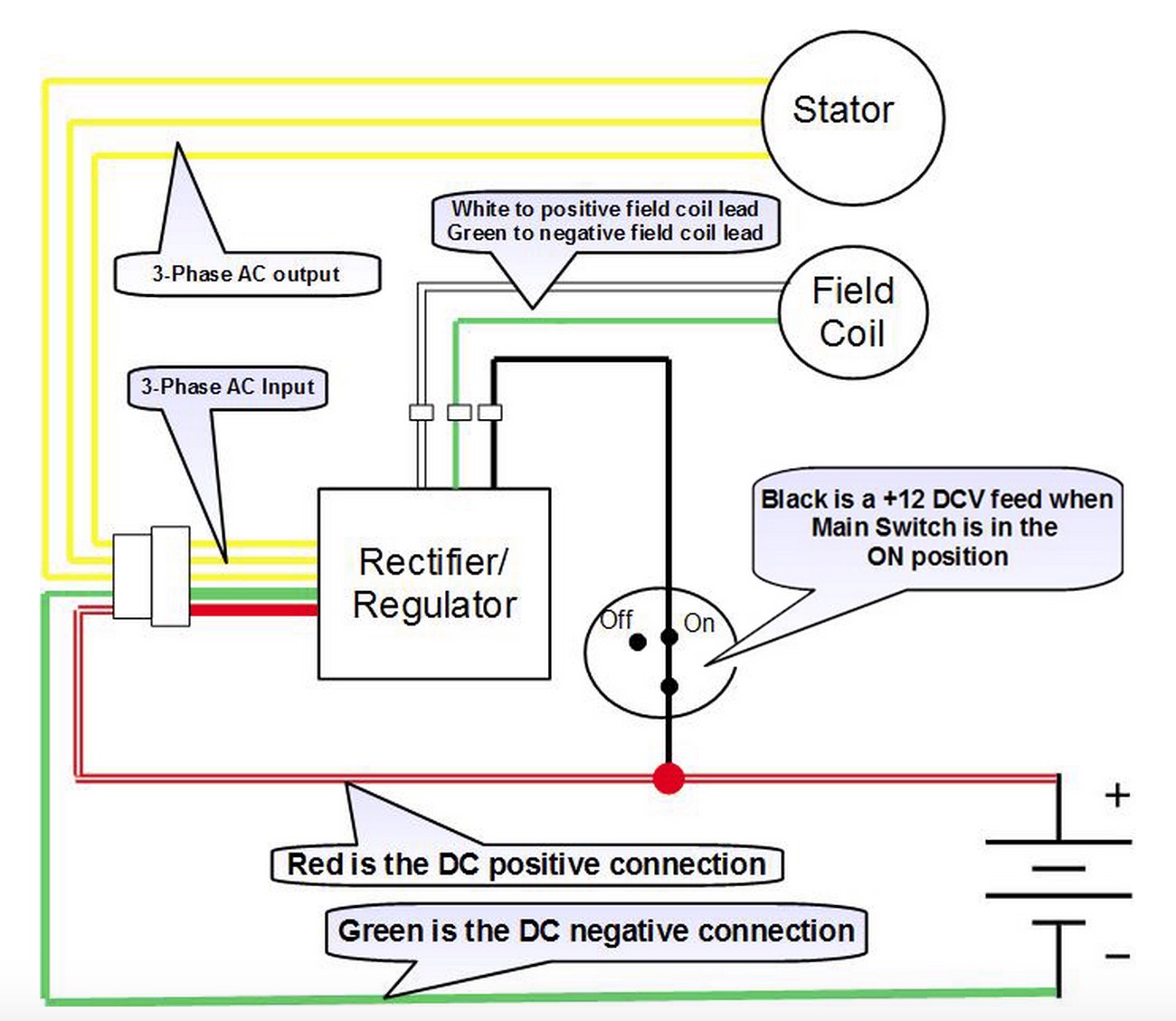
As stated earlier, the lines at a rectifier regulator wiring diagram signifies wires. The wiring diagram i have from a workshop manual shows only two coils (probably for simplification) and one of these is for the ignition system that i don’t intend to modify in any way. This is designed to plug into the stock wiring harness.
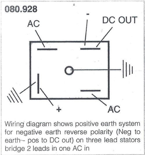
As stated earlier the lines at a rectifier regulator wiring diagram signifies wires. 2 from the alternator, 1 from/to the battery positive, 1 to ground, (negative) and another also to the battery. Yamaha outboard rectifier wiring diagram.
In the manner of grating to remove, replace or repair the wiring in an automobile, having an accurate and detailed 5 wire regulator rectifier. Simply plug the connector onto the 5 pins row and make sure that the pin assignments and wire assignments are matched correctly. ¾many rectifier problems are obvious to the experienced technician upon physical examination.
A rectifier is the part of the charging system that convert the ac voltage from the alternator into dc voltage which can be used to charge. 2 phase 5 wire motorcycle regulator rectifier wiring diagram pdf. April 26, 2021 on 4 pin regulator rectifier wiring diagram.
Wiring diagrams are made up of two things. The circuit form a bridge connecting the four diodes d1 d2 d3 and d4. Occasionally, the cables will cross.
¾carry an inventory of spare parts. Injunction of 2 wires is usually indicated by black dot at the junction of two lines. A wiring diagram is a schematic type that uses abstract illustrated symbols to show all of the components of a system.
Simply plug the connector onto the 5 pins row and make sure that the pin assignments and wire assignments are matched correctly. Many rick s motorsport electrics rectifier regulators eliminate what is commonly referred to as a signal wire on oe pieces. The article provides a detailed explanation regarding the various voltage regulator wiring configurations used in motorcycles.
4 pin regulator rectifier wiring diagram diagram wiring diagram. Wiring diagrams brake rectifiers and coil data. Want to learn more about regulator rectifiers.
Sample motorcycle wiring diagram included in this shipment and dictionary of automotive terms a teacherweb. Lamberts bikes motorcycle part wiring diagrams. The red wire from the rr connects to the red wire in the wiring harness.
According to data we got from google adwords, rapid rectifier wiring diagram has incredibly search online web engine. Voltage regulator voltage regulator rectifier fit. 5 pin rectifier wiring diagram wiring diagram is a simplified agreeable pictorial representation of an electrical circuit it shows the components of the circuit as simplified shapes and the.
M 3 2 2 2 phase 5 wire. It consists of directions and diagrams for various varieties of wiring methods as well as other things like lights, windows, etc. Please insert the diagrams appropriately in the.
Wiring diagram contains numerous in depth illustrations that display the connection of assorted items.
Fast Active Rectifier Circuit Diagram

35 Amp 3Phase Bridge Rectifier Wiring Diagram WindyNation Community Forums
Bridge Rectifier Wiring Diagram Wiring Diagram Schema

Solid State Rectifier BSA Norton Triumph Classic British Spare Parts for Motorcycles in NZ
rectifier wiring

Bridge Rectifier Wiring Diagram For Your Needs

12v Rectifier Regulator Wiring Diagram Wiring Diagram
12v 3 Phase Motorcycle Regulator/rectifier Circuit Wiring Diagram

12 Volt 4 Pin Regulator Rectifier Wiring Diagram For Your Needs

Full Wave Rectifier Circuit Diagram — UNTPIKAPPS

Wiring new rectifier to Indiana 650. 6 wires stock, can I use 5 wire rectifier? Ducati.ms

Roadmaster Wiring Diode Diagram Download

Wiring Diagram Bridge Rectifier For Your Needs

Zener Bridge Rectifier Circuit Diagram
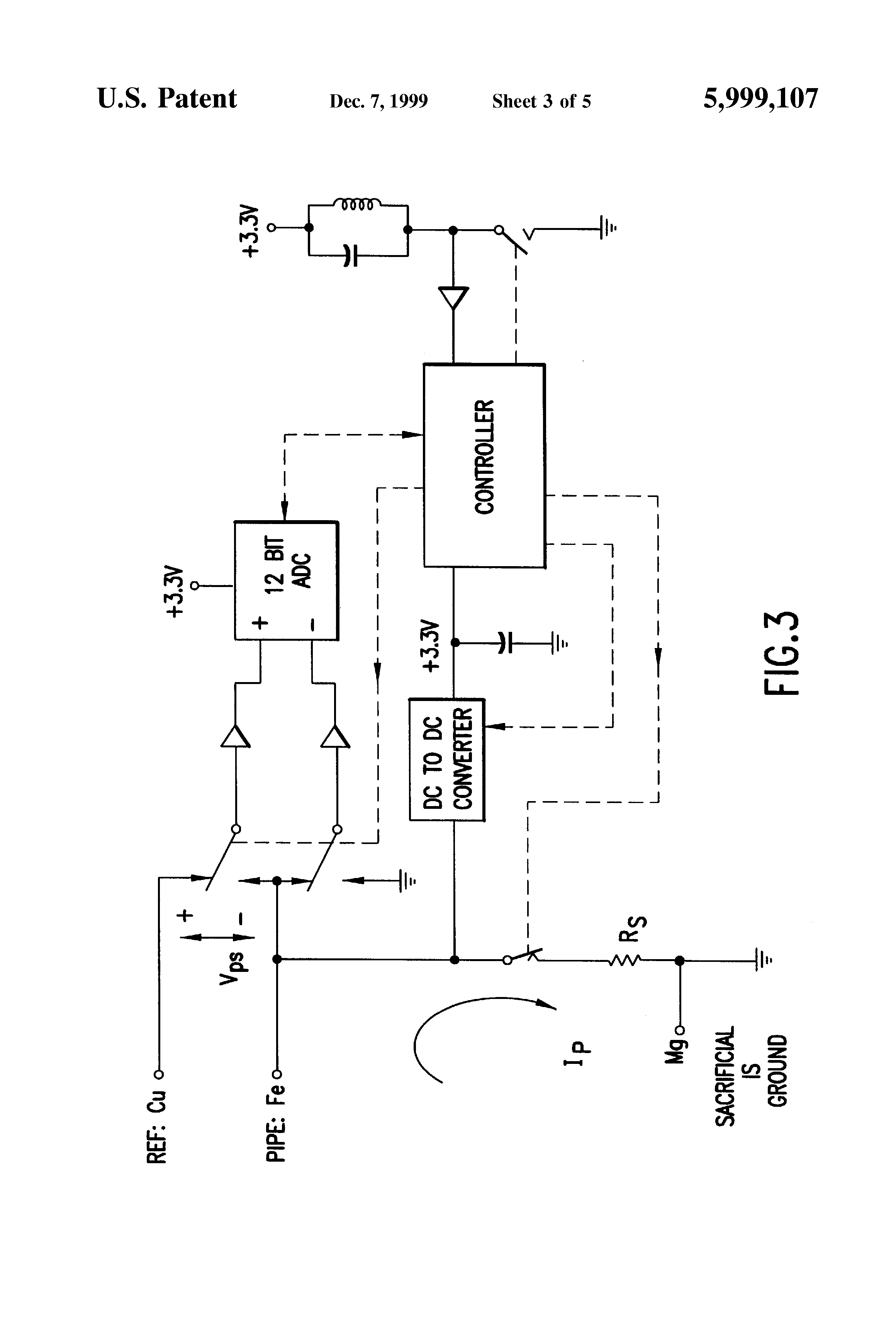
Cathodic Protection Rectifier Wiring Diagram
Aftermarket Honda Regulator Rectifier OEM Style Honda Replacement Part
6 Prong Rectifier Wiring Diagram For 1995 Zx6

Voltage Regulator / rectifier units

Bridge Rectifier Circuit Electronics Basics The Geek Pub